Important Disclaimer

The purpose of this blog is purely to serve as a compilation of good technical material for my students. No financial or other motives are involved. Most of the content in this blog has been reproduced from other sources. I have made every attempt to mention the source link at the beginning of each blog. All readers are requested to kindly acknowledge that source and not this blog, in case you find the post helpful. However, I have not been able to trace the source links for some of my older posts. I wish to emphasize that this is not intentional and any help in this regard would be appreciated.

Nov 7, 2014

Lead Compensator Design

he post below has been copied from: http://thebeautifullmind.com/2012/05/24/lead-compensator-design-with-bode-plot/
In case you find this helpful, please acknowledge the blog above and not this one. The post has been reproduced to help my students understand the concepts and for no other reason.   

The steps to design the Lead Compensator are:
  1. Determine K from the error constants given
  2. Sketch the bode plot
  3. Determine phase margin 
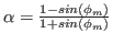
  4. The amount of phase angle to be contributed by lead network is
    $\phi_m=\gamma_{d}-\gamma + \epsilon$, where $\gamma_d$ is the required phase margin and $\epsilon$ is 5 initially. if the angle is greater than 60then we have to design the compensator as 2 cascade compensator with lead angle as $\phi_m/2$
  5. calculate
    $\alpha=\frac{1-sin(\phi_m)}{1+sin(\phi_m)}$ from bode plot find $\omega_m$ such that it is the frequency corresponding to the gain
    $-20log(1/\sqrt(\alpha))$
  6. calculate
    $T=\frac{1}{\omega_m \sqrt(\alpha)}$
  7. a lead compensator has the form
    $\frac{(s+\frac{1}{T})}{(s+\frac{1}{\alpha T})}$
  8. form the complete transfer function with the lead compensator added in series to th original system
  9. plot the new Bode plot and determine phase margin and observe that it is the required phase margin
  10. if not satisfactory repeat steps from step 4 by changing value of $\epsilon$ by 5

Lag Compensator design with Bode plot

The post below has been copied from: http://thebeautifullmind.com/2012/05/23/an-introduction-to-compensator-design-with-matlab/
Please note that in case you find this helpful, please cite  the above source and not this blog post.     

The steps to design the lag Compensator are
  1. Determine K from the error constatns given
  2. Sketch the bode plot
  3. Determine phase margin if it is not satisfactory design lag compensator
  4. take  as the required phase margin to that add a tolerance of 5 so that new phase margin is
    $\gamma_{n}=\gamma_{d}+5$
  5. Find new gain cross over frequency $\omega_{gcn}$ which is the frequency corresponding to $\gamma_n$ of previous step for that find
    $\phi_{gcn}=\gamma_n - 180$ from the bode plot determine $\omega_{gcn}$corresponding to $\phi_{gcn}$
  6. Determine gain corresponding to $\omega_{gcn}$ from bode plotlet it be A db
  7. a lag compensator has the form
    $\frac{(s+\frac{1}{T})}{(s+\frac{1}{\beta T})}$

  8. $\beta=10^{\frac{A}{20}}$ since
    $A = 20log\beta$

  9. $T= \frac{10}{\omega_{gcn}}$
  10. form the complete transfer function with the lag compensator added in series to th original system
  11. plot the new Bode plot and determine phase margin and observe that it is the required phase margin

Oct 24, 2013

RTD

The following post has been taken from the web page : http://www.omega.com/temperature/z/thertd.html
Kindly acknowledge the above page and not this blog if you find the post useful. The contents have been reproduced here as a reference study material for my students.


Meyers RTD Construction


History

The same year that Seebeck made his discovery about thermoelectricity, Sir Humphrey Davy announced that the resistivity of metals showed a marked temperature dependence. Fifty years later, Sir William Siemens proffered the use of platinum as the element in a resistance thermometer. His choice proved most propitious, as platinum is used to this day as the primary element in all high-accuracy resistance thermometers. In fact, the Platinum Resistance Temperature Detector, or PRTD, is used today as an interpolation standard from the oxygen point (-182.96°C) to the antimony point (630.74°C).


Platinum is especially suited to this purpose, as it can withstand high temperatures while maintaining excellent stability. As a noble metal, it shows limited susceptibility to contamination.

The classical resistance temperature detector (RTD) construction using platinum was proposed by C.H. Meyers in 1932. He wound a helical coil of platinum on a crossed mica web and mounted the assembly inside a glass tube. This construction minimized strain on the wire while maximizing resistance.

Although this construction produces a very stable element, the thermal contact between the platinum and the measured point is quite poor. This results in a slow thermal response time. The fragility of the structure limits its use today primarily to that of a laboratory standard.

Another laboratory standard has taken the place of Meyers’ design. This is the bird-cageelement proposed by Evans and Burns. The platinum element remains largely unsupported, which allows it to move freely when expanded or contracted by temperature variations.

Strain-induced resistance changes over time and temperature are thus minimized, and the bird-cage becomes the ultimate laboratory standard. Due to the unsupported structure and subsequent susceptibility to vibration, this configuration is still a bit too fragile for industrial environments.

A more rugged construction technique is shown in Figure 37. The platinum wire is bifilar wound on a glass or ceramic bobbin. The bifilar winding reduces the effective enclosed area of the coil to minimize magnetic pickup and its related noise. Once the wire is wound onto the bobbin, the assembly is then sealed with a coating of molten glass. The sealing process assures that the RTD will maintain its integrity under extreme vibration, but it also limits the expansion of the platinum metal at high temperatures. Unless the coefficients of expansion of the platinum and the bobbin match perfectly, stress will be placed on the wire as the temperature changes, resulting in a strain-induced resistance change. This may result in a permanent change in the resistance of the wire.

There are partially supported versions of the RTD which offer a compromise between the bird-cage approach and the sealed helix. One such approach uses a platinum helix threaded through a ceramic cylinder and affixed via glass-frit. These devices will maintain excellent stability in moderately rugged vibrational applications.


TYPICAL RTD’s (FIgures 36 and 37) 

Typical RTD's - Typical RTD Probes, Thick Film Omega Film Element, Glass sealed Biflar Winding, Thin Film Omega TFD Element


Metal Film RTD’s

In the newest construction technique, a platinum or metal-glass slurry film is deposited or screened onto a small flat ceramic substrate, etched with a lasertrimming system, and sealed. The film RTD offers substantial reduction in assembly time and has the further advantage of increased resistance for a given size. Due to the manufacturing technology, the device size itself is small, which means it can respond quickly to step changes in temperature. Film RTD’s are presently less stable than their hand-made counterparts, but they are becoming more popular because of their decided advantages in size and production cost. These advantages should provide the impetus for future research needed to improve stability.

Metals - All metals produce a positive change in resistance for a positive change in temperature. This, of course, is the main function of an RTD. As we shall soon see, system error is minimized when the nominal value of the RTD resistance is large. This implies a metal wire with a high resistivity. The lower the resistivity of the metal, the more material we will have to use.

Table 6 lists the resistivities of common RTD materials.
METALRESISTIVITY OHM/CMF
(cmf = circular mil foot)


Gold
Silver
Copper
Platinum
Tungsten 
Nickel
Au
Ag
Cu
Pt
w
Ni
13.00
8.8
9.26
59.00
30.00
36.00

Table 6


Because of their lower resistivities, gold and silver are rarely used as RTD elements. Tungsten has a relatively high resistivity, but is reserved for very high temperature applications because it is extremely brittle and difficult to work.

Copper is used occasionally as an RTD element. Its low resistivity forces the element to be longer than a platinum element, but its linearity and very low cost make it an economical alternative. Its upper temperature limit is only about 120ºC.

The most common RTD’s are made of either platinum, nickel, or nickel alloys. The economical nickel derivative wires are used over a limited temperature range. They are quite non-linear and tend to drift with time. For measurement integrity, platinum is the obvious choice.


Resistance Measurement

The common values of resistance for a platinum RTD range from 10 ohms for the bird-cage model to several thousand ohms for the film RTD. The single most common value is 100 ohms at 0ºC. The DIN 43760 standard temperature coefficient of platinum wire is α = .00385. For a 100 ohm wire, this corresponds to + 0.385 ohms/ºC at 0ºC. This value for α is actually the average slope from 0ºC to 100ºC. The more chemically pure platinum wire used in platinum resistance standards has an α of +.00392 ohms/ohm/ºC.

Both the slope and the absolute value are small numbers, especially when we consider the fact that the measurement wires leading to the sensor may be several ohms or even tens of ohms. A small lead impedance can contribute a significant error to our temperature measurement.
EFFECT OF LEAD RESISTANCE


A ten ohm lead impedance implies 10/.385 ≈ 26ºC error in measurement. Even the temperature coefficient of the lead wire can contribute a measurable error. The classical method of avoiding this problem has been the use of a bridge.
WHEATSTONE BRIDGE


The bridge output voltage is an indirect indication of the RTD resistance. The bridge requires four connection wires, an external source, and three resistors that have a zero temperature coefficient. To avoid subjecting the three bridge-completion resistors to the same temperature as the RTD, the RTD is separated from the bridge by a pair of extension wires:
Figure 40


These extension wires recreate the problem that we had initially: The impedance of the extension wires affects the temperature reading. This effect can be minimized by using a three-wire bridge configuration:
3-WIRE BRIDGE


If wires A and B are perfectly matched in length, their impedance effects will cancel because each is in an opposite leg of the bridge. The third wire, C, acts as a sense lead and carries no current.

The Wheatstone bridge shown in Figure 41 creates a non-linear relationship between resistance change and bridge output voltage change. This compounds the already non-linear temperature-resistance characteristic of the RTD by requiring an additional equation to convert bridge output voltage to equivalent RTD impedance.

4-Wire Ohms - The technique of using a current source along with a remotely sensed digital voltmeter alleviates many problems associated with the bridge.
4-WIRE OHMS MEASUREMENT


The output voltage read by the dvm is directly portional to RTD resistance, so only one conversion equation is necessary. The three bridge-completion resistors are replaced by one reference resistor. The digital voltmeter measures only the voltage dropped across the RTD and is insensitive to the length of the lead wires.

The one disadvantage of using 4-wire ohms is that we need one more extension wire than the 3-wire bridge. This is a small price to pay if we are at all concerned with the accuracy of the temperature measurement.
Figure 43


3-Wire Bridge Measurement Errors

If we know VS and VO, we can find Rg and then solve for temperature. The unbalance voltage Vo of a bridge built with R1 = R2 is:


If Rg = R3, VO= 0 and the bridge is balanced. This can be done manually, but if we don’t want to do a manual bridge balance, we can just solve for Rg in terms of VO:


This expression assumes the lead resistance is zero. If Rg is located some distance from the bridge in a 3-wire configuration, the lead resistance RL will appear in series with both Rg and R3:
Figure 44


Again we solve for Rg:


The error term will be small if Vo is small, i.e., the bridge is close to balance. This circuit works well with devices like strain gauges, which change resistance value by only a few percent, but an RTD changes resistance dramatically with temperature. Assume the RTD resistance is 200 ohms and the bridge is designed for 100 ohms:
Figure 45


Since we don’t know the value of RL, we must use equation (a), so we get:


The correct answer is of course 200 ohms. That’s a temperature error of about 2.5ºC.

Unless you can actually measure the resistance of RL or balance the bridge, the basic 3-wire technique is not an accurate method for measuring absolute temperature with an RTD. A better approach is to use a 4-wire technique.

Resistance to Temperature Conversion

The RTD is a more linear device than the thermocouple, but it still requires curve-fitting. The Callendar-Van Dusen equation has been used for years to approximate the RTD curve:


Where:

RT=Resistance at Temperature T
Ro=Resistance at T = 0ºC
α=Temperature coefficient at T = 0ºC ((typically +0.00392Ω/Ω/ºC))
δ=1.49 (typical value for .00392 platinum)
β=0    T > 0
0. 11    (typical) T < 0


The exact values for coefficients α , β, and δ are determined by testing the RTD at four temperatures and solving the resultant equations. This familiar equation was replaced in 1968 by a 20th order polynomial in order to provide a more accurate curve fit. The plot of this equation shows the RTD to be a more linear device than the thermocouple.

Jun 29, 2013

Online computation of mean and variance- Matlab

Finding the mean and std. deviation online is important when it is not possible to store the entire set of values in the memory (say in case of microcontrollers) or when dealing with an incoming stream of values. Below is a code in Matlab for online computation of mean and std. deviation. I have written this based on the algo. given in wikipedia. The logic used in this Matlab code can be used to write code for your microcontroller program. The code:

% online computation of mean and variance
% By Binoy
% for this, you need to know only x(n-1) and x(n) values
% every time a new value comes in, mean and variance are computed
clear all;
clc
prompt = 'What is the number of samples? ';
samples = input(prompt)

prompt_1 = 'input the first sample ';
x_1 = input(prompt_1)

mean_x=x_1;
S_x=0;
for n=2:samples
    prompt_2 = 'input the sample ';
    x = input(prompt_2)
   
    mean_x_n_minus_1= mean_x;
    mean_x= mean_x+((x-mean_x_n_minus_1)/n) % the mean
    S_x= S_x+((x-mean_x_n_minus_1)*(x-mean_x));
    var_x=S_x/(n-1)% the variance
   
   
    end